Quantization error
In analog-to-digital conversion, the difference between the actual analog value and quantized digital value is called quantization error or quantization distortion. This error is either due to rounding or truncation. The error signal is sometimes considered as an additional random signal called quantization noise because of its stochastic behaviour.
Contents |
Quantization error models
In the typical case, the original signal is much larger than one LSB. When this is the case, the quantization error is not significantly correlated with the signal, and has an approximately uniform distribution. In the rounding case, the quantization error has a mean of zero and the RMS value is the standard deviation of this distribution, given by  . In the truncation case the error has a non-zero mean of
  and the RMS value is
  . In the eight-bit ADC example, the RMS rounding error represents 0.113% of the full signal range.
At lower amplitudes the quantization error becomes dependent on the input signal, resulting in distortion. This distortion is created after the anti-aliasing filter, and if these distortions are above 1/2 the sample rate they will alias back into the audio band. In order to make the quantization error independent of the input signal, noise with an amplitude of 2 least significant bits is added to the signal. This slightly reduces signal to noise ratio, but, ideally, completely eliminates the distortion. It is known as dither.
Quantization noise model
Quantization noise is a model of quantization error introduced by quantization in the analog-to-digital conversion (ADC) in telecommunication systems and signal processing. It is a rounding error between the analog input voltage to the ADC and the output digitized value. The noise is non-linear and signal-dependent. It can be modelled in several different ways.
In an ideal analog-to-digital converter, where the quantization error is uniformly distributed between −1/2 LSB and +1/2 LSB, and the signal has a uniform distribution covering all quantization levels, the Signal-to-quantization-noise ratio (SQNR) can be calculated from

Where Q is the number of quantization bits.
The most common test signals that fulfill this are full amplitude triangle waves and sawtooth waves.
For example, a 16-bit ADC has a maximum signal-to-noise ratio of 6.02 × 16 = 96.3 dB.
When the input signal is a full-amplitude sine wave the distribution of the signal is no longer uniform, and the corresponding equation is instead

Here, the quantization noise is once again assumed to be uniformly distributed. When the input signal has a high amplitude and a wide frequency spectrum this is the case.[1] In this case a 16-bit ADC has a maximum signal-to-noise ratio of 98.09 dB. The 1.761 difference in signal-to-noise only occurs due to the signal being a full-scale sine wave instead of a triangle/sawtooth.
Quantization noise power can be derived from
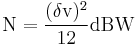
where  is the voltage of the level.
(Typical real-life values are worse than this theoretical minimum, due to the addition of dither to reduce the objectionable effects of quantization, and to imperfections of the ADC circuitry. On the other hand, specifications often use A-weighted measurements to hide the inaudible effects of noise shaping, which improves the measurement.)
For complex signals in high-resolution ADCs this is an accurate model. For low-resolution ADCs, low-level signals in high-resolution ADCs, and for simple waveforms the quantization noise is not uniformly distributed, making this model inaccurate.[2] In these cases the quantization noise distribution is strongly affected by the exact amplitude of the signal.
The calculations above, however, assume a completely filled input channel. If this is not the case - if the input signal is small - the relative quantization distortion can be very large. To circumvent this issue, analog compressors and expanders can be used, but these introduce large amounts of distortion as well, especially if the compressor does not match the expander.
Other fields
Many physical quantities are actually quantized by physical entities. Examples of fields where this limitation applies include electronics (due to electrons), optics (due to photons), biology (due to DNA), and chemistry (due to molecules). This is sometimes known as the "quantum noise limit" of systems in those fields. This is a different manifestation of "quantization error," in which theoretical models may be analog but physically occurs digitally. Around the quantum limit, the distinction between analog and digital quantities vanishes.
See also
References
- ^ Pohlman, Ken C. (1989). Principles of Digital Audio 2nd Edition. SAMS. p. 60. http://books.google.com/books?id=VZw6z9a03ikC&pg=PA37&source=gbs_selected_pages&cad=0_1.
- ^ okelloto, tom (2001). The Art of Digital Audio 3rd Edition. Focal Press. ISBN 0240515870.
External links
- Quantization noise in Digital Computation, Signal Processing, and Control, Bernard Widrow and István Kollár, 2007.
- The Relationship of Dynamic Range to Data Word Size in Digital Audio Processing
- Round-Off Error Variance — derivation of noise power of q²/12 for round-off error
- Dynamic Evaluation of High-Speed, High Resolution D/A Converters Outlines HD, IMD and NPR measurements, also includes a derivation of quantization noise
- Signal to quantization noise in quantized sinusoidal
|
||||||||||||||||||||